Since my last post (in March…) I’ve spent a lot of time tweaking and hacking my 3D printer to get it as accurate and reliable as possible; it’s still not quite as good as I’d prefer, but I’m getting Good Enough results now…
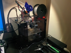
Makibox A6HT + E3D v5 hotend + Greg/Wade Extruder + Z-wobble eliminator + aluminium rod-couplings + Airtripper Pocket Filament Reel Holders
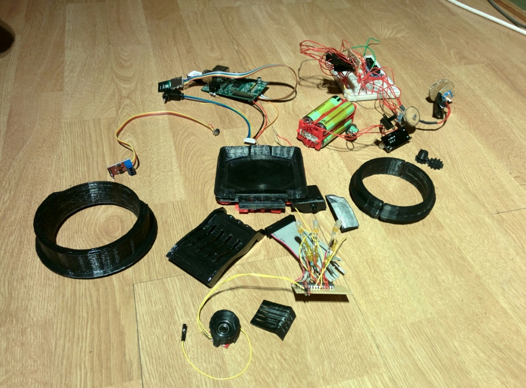
I’ve accumulated a good collection of components:
The 3D-modelling work, isn’t quite finalised, but here’s an explodey animation of how it currently stands:
The unit will be powered by 18650 Li-Ion batteries – wired to provide about 8V in series, giving plenty of current when stepped down to the system’s 5V.
Here’s the battery-pack I designed, including the charging circuit and power regulator module:
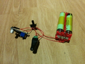
4x Panasonic 18650 cells, 7.4v battery input/output board, LM2596 adjustable regulator, switch, barrel-jack socket
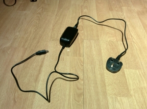
I originally intended to allow the batteries to be charged via a 5V USB power-supply – I was hoping to just include the circuitry from a battery-pack I’d bought, but that couldn’t provide enough current for as long I wanted, so I’m now using an 8V mains-charger intended to charge bike-lights:
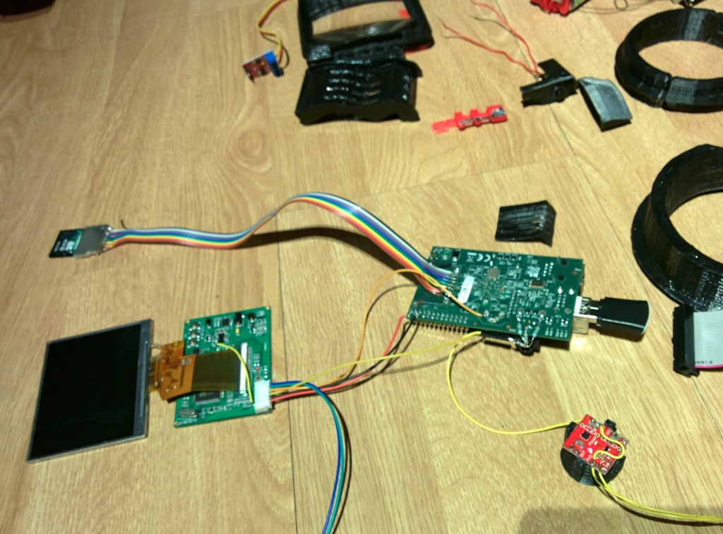
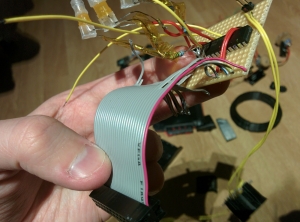
The Raspberry Pi at the heart of the unit is now a Frankensteinian mess of soldering/unsoldering:
The original SD-card socket broke, so I replaced it with a new one on a ribbon-cable, which allows me to put that somewhere easier to access.
After I had to make that repair I didn’t mind making other changes to the board 😉
I’m going to put the USB-ports on a cable too, to move them out of the way and to slim down the board some more.
I’ve soldered some resistors to the audio-out pads to convert audio to mono before feeding it to the red amplifier-module (sitting on printed speaker/horn assembly)
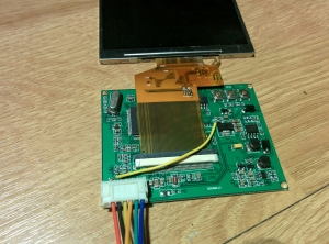
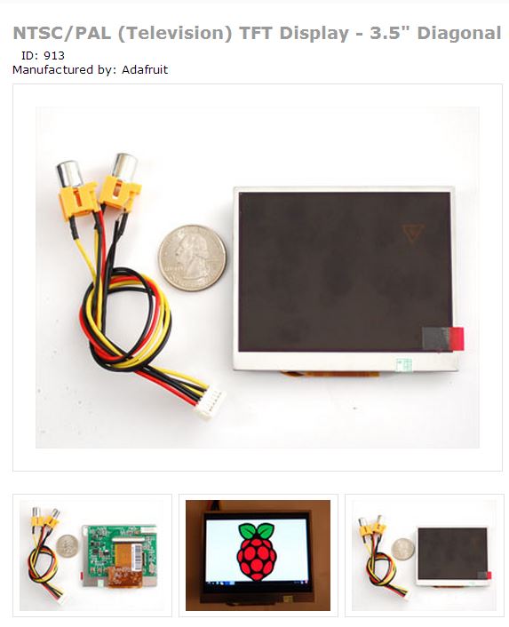
I’ve bypassed the power-regulator on the monitor’s driver-board, to feed it 5V directly from the Pi:
(I tried using this board’s regulator to power the rest of the system, but it wasn’t quite powerful enough)
I was previously going to run all the electronics off a Teensy board, via one of the RasPi’s USB ports, but I’m now going to do so directly through the Pi’s GPIO port, with a port-expander chip to give me the extra pins I need:
I’ve decided not to use the GPS module that I had working with the Pip-Boy’s map – it doesn’t work well indoors, so it just seemed like a waste of power…
Instead, I’ve been working on a method to get location-data out of my phone via its shared Wifi connection instead – this works much better when indoors, as it can use cell-towers to provide a rough location estimate.
