Pip-Boy 3000

All posts tagged Pip-Boy 3000

Since my last post (in March…) I’ve spent a lot of time tweaking and hacking my 3D printer to get it as accurate and reliable as possible; it’s still not quite as good as I’d prefer, but I’m getting Good Enough results now…

I’ve accumulated a good collection of components:

wpid-wp-1413225090009.jpeg

The 3D-modelling work, isn’t quite finalised, but here’s an explodey animation of how it currently stands:

The unit will be powered by 18650 Li-Ion batteries – wired to provide about 8V in series, giving plenty of current when stepped down to the system’s 5V.

Here’s the battery-pack I designed, including the charging circuit and power regulator module:

Battery bits

4x Panasonic 18650 cells, 7.4v battery input/output board, LM2596 adjustable regulator, switch, barrel-jack socket

I originally intended to allow the batteries to be charged via a 5V USB power-supply – I was hoping to just include the circuitry from a battery-pack I’d bought, but that couldn’t provide enough current for as long I wanted, so I’m now using an 8V mains-charger intended to charge bike-lights:

The Raspberry Pi at the heart of the unit is now a Frankensteinian mess of soldering/unsoldering:

wpid-wp-1413233675088.jpeg

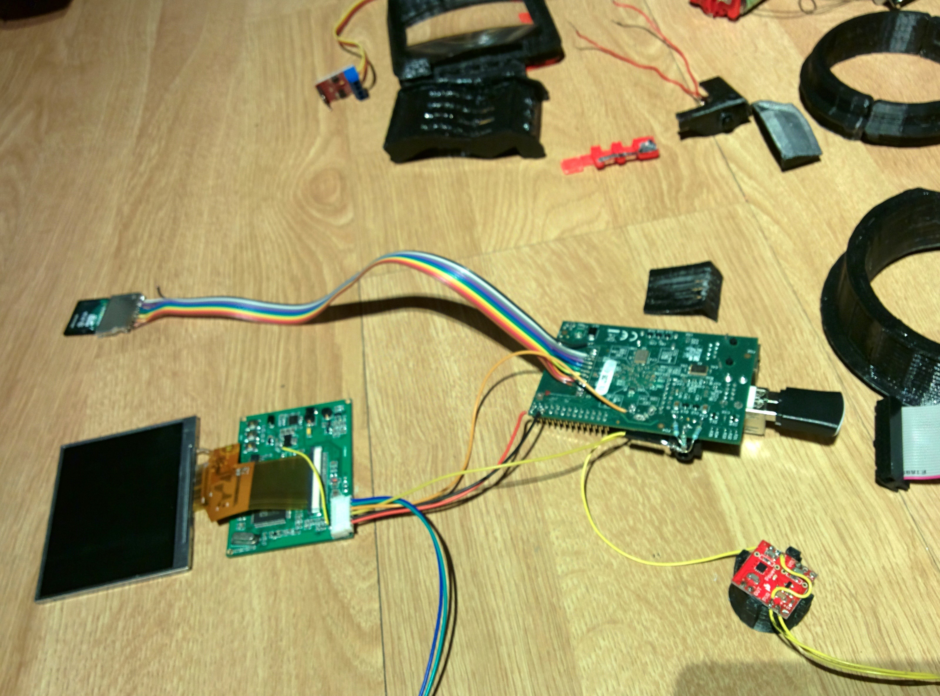
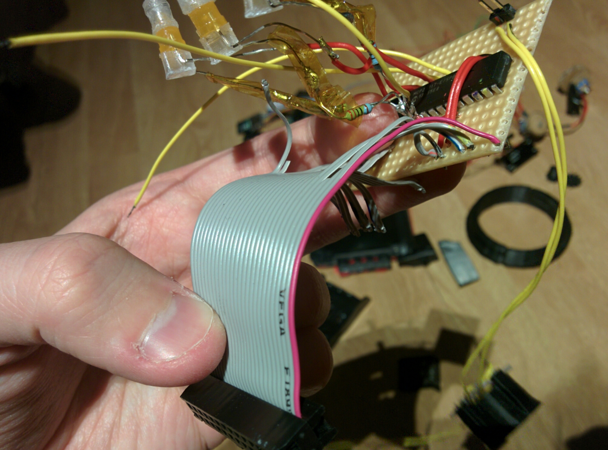
The original SD-card socket broke, so I replaced it with a new one on a ribbon-cable, which allows me to put that somewhere easier to access.

After I had to make that repair I didn’t mind making other changes to the board 😉

I’m going to put the USB-ports on a cable too, to move them out of the way and to slim down the board some more.

I’ve soldered some resistors to the audio-out pads to convert audio to mono before feeding it to the red amplifier-module (sitting on printed speaker/horn assembly)

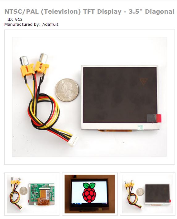
I’ve bypassed the power-regulator on the monitor’s driver-board, to feed it 5V directly from the Pi:

wpid-wp-1413225533714.jpeg

(I tried using this board’s regulator to power the rest of the system, but it wasn’t quite powerful enough)

I was previously going to run all the electronics off a Teensy board, via one of the RasPi’s USB ports, but I’m now going to do so directly through the Pi’s GPIO port, with a port-expander chip to give me the extra pins I need:

wpid-wp-1413225361933.jpeg

I’ve decided not to use the GPS module that I had working with the Pip-Boy’s map – it doesn’t work well indoors, so it just seemed like a waste of power…

Instead, I’ve been working on a method to get location-data out of my phone via its shared Wifi connection instead – this works much better when indoors, as it can use cell-towers to provide a rough location estimate.

The first thing I had to do when designing my Pip-Boy was choose an appropriately-sized screen that I could connect to my Raspberry Pi.

I chose this screen from the marvelous Adafruit – it was about the right size, and it takes a composite-video input:

This screen and its driver-board were probably originally intended for use in an in-car monitor, for a reversing-camera or maybe for a portable DVD-player – it requires 6-12v of power to run, but I reckoned I ought to be able to supply that from some batteries.

The screen’s resolution is quite low (320×240) but that’s just fine for my purposes.

While waiting for that to arrive from far-off New York, I then searched for a rectangular lens to lay over the screen, to give the effect of a curved monitor.

After failing trying to find a cheap separate lens with the right shape and aspect-ratio, I ended up doing what a previous builder had done, and bought likely-looking cheap second-hand slide-viewer from Ebay, which I dismantled.

Photax Solar slide-viewer

Photax Solar slide-viewer

This slide-viewer contains two chunky plastic lenses, and the largest of the lenses was just the right size and shape for what I needed:

A scale image of the in-game Pip-Boy 3000 - plus models of a Raspberry Pi, Adafruit 3.5" monitor, and the lens I took from a slideviewer

A scale image of the in-game Pip-Boy 3000 – plus models of a Raspberry Pi, Adafruit 3.5″ monitor, and the lens I’d taken from a slideviewer

I was pleased to find that I could slot the screen into the slide-viewer where its smaller interior lens originally sat – making a delightful little CRT-looking monitor!

In order to get the RasPi to output to the full screen (i.e. no black borders) I edited its config.txt file with the following lines uncommented/changed:

framebuffer_width=640
framebuffer_height=480
disable_overscan=1
overscan_left=36
overscan_right=18
overscan_top=0
overscan_bottom=0
sdtv_mode=2

That combination of overscan/disabled options might seem a bit weird, but it allowed me to fill the whole of the TFT.

You’ll see that I’ve set it to use twice the screen’s resolution – I found that PyGame (which I’m using to draw the UI graphics) didn’t work right when the system-resolution was lower than 640×480.

The console-text and Xwindows are still just about readable at that resolution, if you squint carefully!

Coming up… how I modified this 6-12v screen to work on the RasPi’s 5v power-supply!

As I mentioned in this blog’s first post, a few years ago I built myself a replica of the Pip-Boy 3000 from the game Fallout 3 – mainly crafted from card, glue, expanding-foam and spraypaint:

My older non-working Pip-Boy 3000

I used my Iphone for the screen, which allowed me to simulate the in-game interface by playing videos – animated scanlines and background humming noise added to the authenticity.

The screen was flat – unlike the slightly-rounded CRT of the in-game model…  plus the prop was about 20% bigger than the “real” Pip-Boy, because I’d scaled the model to fit the phone.

Oh well, nothing I could do about that – even if I could find a super-thin CRT, I don’t think that’d fit into my limited budget, and I wouldn’t want to strap it too my arm!

Flash forward a few years… I saw a link to Zachariah Perry’s Pip-Boy build, showing off a cleverly-faked curved screen – ahah, very clever!

His version, based on a cast of the official Limited Edition alarm-clock, has a screen taken from a digital photo-frame, seen through a rectangular lens taken from an old slide-viewer.

This got me thinking… I was waiting on the 3D printer I had ordered/funded last year, so I might as well start reworking my old Pip-Boy 3D model, and get it ready for printing in plastic…

But this time I’d do it to a more accurate scale, and build it around a nice fake-CRT screen.

Since I still expected to wait a while until the printer was ready, I would concentrate on working on the internals first, in order to work out exactly how much I needed to fit inside.

I now had experience with the Raspberry Pi and Teensy boards, and had seen pictures of Ryan Grieve’s Raspberry Pipboy build, so I thought I might as well make this a fully-working prop too!

Ok, that’s where I started out, many months ago – now I can get onto writing some more detailed and (hopefully) useful posts: I’ve learned a lot about electronics and stuff while working on this project, and hope to share some of the tips and tricks I’ve picked up along the way!

Pip-Boy 3000 icon

(BTW, my Makibox is currently en-route, via a slow boat from Hong Kong;  Soon, sooon…)

Hi folks,

I’ve been making various things over the years.
I’ve not been documenting them super-good.

Let’s start a blog!
I’ve not used WordPress before, so this could get messy…

I’ll give you more interesting posts in future, but I’ll start you off with some snippets from recent projects:

I’ve been working on making my very own “working” Pip-Boy 3000 (as seen in the game Fallout 3) using a Raspberry Pi as its brain:

(the latest version of the software is uploaded to my BitBucket)

That’s my second attempt at making a Pip-Boy, I made a non-working version (plus matching Vault Suit) four years ago:
The Lone Wanderer

I’ve recently been working on building/programming a four-legged robot, which I’ve dubbed The TetraQuad:

I’m also planning to build a 5x5x5 RGB LED cube: